9 minutes
An Introduction to Light Sources
This is an updated repost of my deactivated old blog or from notes of past my studies. The date follows the original time of writing
Welcome to my reflections!
Today we dive right in the topic of light sources, we’re going to study the 3 basic light sources used more frequently in real-time rendering: omni, spot and directional light sources; understand the theory behind them and when to use each of the three based on the scene description. Is important to note that omni and spot light sources are both point-light sources – them don’t have finite area, in another words: the entire source is located at a point in space. The directional light source in another hand is treated differently as it don’t have a location per se. So, without further ado let’s start, as we all know this isn’t a Dream Theater’s track introduction!
Point-Light Sources
We start with point light sources, without any doubt the most used light source in real-time rendering! Right now, take a look around, you’ll see that there ins’t such thing as an point light source, all light-sources in real-live environment poesses area and shape, so what about point light sources? What actually happens is the use of an approximation based under the following assumption: the distance between the source point s and the shaded point p is greater compared to the object being shaded itself. Using this assumption we can simulate light-source without worrying about the complications shape and area variation. By the way, this light-sources are called area-light sources and are very useful and realistic, I pretend write a post specific for area-light sources soon. Well, as stated before point light sources can be divided into two major source types: omni and spot. Let’s first take a look at the omni light source case.
Omni Light Sources
First lets understand why this name. Omni means “of all things”, in our case omni has to do with the fact that the light source has no directional variation in intensity, only spatial. Therefore we can see omni light source as sources that emanates radiation equally in all directions. See figure 1, which illustrate this fact geometrically.

Well, we saw the description of how omni lights works, now is time to see how to represent them: We know that point-light sources don’t have area, so we can leave it behind, we also know that omni-light sources don’t have directional variation, therefore any directional vector won’t be necessary either, this leave us with position and color (irradiance in our case). We now that the color can be represented with an RGB vector, very simple, the spatial variation in another hands need a little more information with it than only the light position itself, some way to account the distance of the shaded point from the light source, how the intensity fades with it. We need a falloff function!
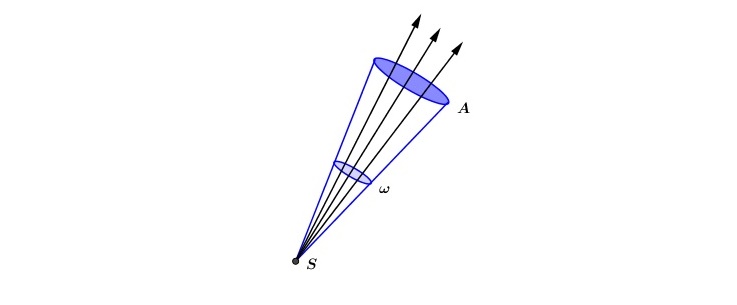
Physically speaking point light sources falls with the inverse-square law, but in reality we don’t use it instead we prefer a different function, but before we talk about why choose another function lets see the reason behind the \(\frac{1}{r^2}\). Isn’t very hard to proof the inverse-square law to point light sources, is as follow (See Figure 2 bellow): Imagine a point light source S emanating radiation radially, if we pick a surface element ω of an sphere centered at S with radius 1 and another sphere also centered at S but with radius r we can use proportion to see that the area element A on this new sphere is proportional to \(r^2\), but the rays density in this direction is constant therefore the rays through A are the same rays through ω, thus the intensity of rays are proportional to \(\frac{1}{r^2}\). See equation 1 for the mathematical definition.
\[ \frac{A}{\omega} = \frac{4\pi r^{2}}{4\pi} = r^{2} \implies A = r^{2}\omega \tag{1}\]

Even though we known that the inverse-square law is physically correct for this case we prefer to use others falloff functions – I put others because there are some different variations used both in the real-time and offline world. Here we’ll use the same used in the Real-Time Rendering Third edition textbook, also used for calculate the linear fog falloff:
\[ f(r) = \frac{r_{max} - r}{r_{max} - r_{min}} \tag{2}\]
This function works as follow (Now is a good moment to take a look at Figure 1 again): If you have 2 cutoff distances \(r_{min}\) and \(r_{max}\) you can define the falloff function in the following way: If the distance \(r\) is less than \(r_{min}\) then the intensity is maximum, if \(r\) is between \(r_{min}\) and \(r_{max}\) then use the falloff function above and last but not least if \(r\) is greater than \(r_{max}\) then the intensity is minimum. But what about the WHY use this functions instead of the inverse-square law? Well the first thing is the fact that this function reaches 0 intensity, so we can cut objects after a certain distance reducing the amount of computation necessary, another point is overflow; with the inverse-square law we didn’t have a maximum value for the intensity, therefore the values could get really big with \(r\) very small and messy with the computations.
An important tool to always have in our pockets is the notion of approximation, even though sometimes we work the physics and get the right results, when implementing things can just not work out, in this kind of situations we need to make some additional assumptions, but always trying to be as physically-correct as possible.
Well, we’re done with omni light sources, but not with point-light sources. Now is time to discuss spot light sources, is time to vary intensity with direction! But before we go take a look at figure 3.

Spot Light Sources
Enter the Spot light! Now is time to talk about point light sources with directional variation – the ones you see in nearly all metal shows – approximation remember? Until now we only looked at intensity variation relative to distance, even though this representation is useful and important not all light effects can be simulated by it, therefore we need to develop a new mathematical model that account for others variations, in our case angular. See the example bellow:

Actually there isn’t much ground to cover here, the more mathematical background is already filled. The point to make is how we can represent the angular variation, and the answer is another falloff function, the idea is the same as before: Keep some minimum intensity, use the falloff to vary the intensity between the max and min, and also keep some maximum intensity for the light source.
So, what about this new fallout function? Well, keep an eye at figure 5 while reading the explanation, ok?

First of all, we’ll assume that the cosine function will only receive input in the interval \([0,π]\), this make total sense to the ideia of an spot-light – to direct the light, not radiate it radially as in the omni case! Think of an spot-light if you having doubts about this. Well, with this point made we can start the discussion about the falloff function itself. The first thing to note are the angles, we have \(θ_u\), \(θ_p\) and \(θ_i\):
- \(θ_u\) is the umbra angle and it is the cutoff to the minimum – if you angle is greater than it, then you are in minimum intensity.
- \(θ_p\) is the penumbra angle, it is the mediator between the maximum and the falloff function. If you angle is greater than \(θ_p\) and smaller than \(θ_u\) you are in the falloff, otherwise you’re inside the maximum range.
- \(θ_i\) is the guy that varies, it represent the angle between the direction of light’s propagation \(s\) and the light-to-point direction \(-l\) (pay attention to the minus sign) – this is the classic \(l\) vector we use to compute the diffuse light dot product \(\hat{n}.\hat{l}\), but here we invert the direction because we going from the light to the point (see figure 5).
The last thing we need to take care before looking at the function is the relation of the cosine function with its input angle. As we all now the cosine function decreases between \(0\) and \(\pi\), therefore the greater the angle the smaller the cosine value. With that fact in mind we move to the next step.
After all this prelude we finally look at falloff (See Equation 3 bellow). It’s actually a pretty simple function as it follows the same pattern than equation 2, but now the cutoffs are cosines – remember \(θ_p\) and \(θ_u\)! (I let to the reader the task to put it all together and make sense of the central part of the equation – the ratio inside, as it is the most important part of understand its mathematical representation).
\[ f(\theta_{i}) = \frac{cos{\theta_{i}} - cos{\theta_{u}}}{cos{\theta_{p}} - cos{\theta_{u}}}t \tag{3} \]
Finally the \(t\) parameter! Well, the \(t\) is actually pretty easy to understand – just remember the classic exponent on the specular Blinn-Phong term -. Its main function is to help control the thickness of the ring between the maximum and minimum (Figure 4 can help). The greater the \(t\) the thinner is the ring. One way to visualize it is as follow: The falloff function is always between 0 and 1, and we all now that if some x is in this interval \(x^{²}\) also is, but isn’t just that. Actually \(…. < x^{3} < x^{²} < x^{1}\), so the greater \(t\) the faster the falloff function reaches the minimum. Take a look at the figure bellow.

That is it about point light sources crew, we’ve only one more boldly light source to check before the take-off!
Directional Light Sources
Last but not least, the directional light source! This actually is the simplest of the two, we only need an constant vector to represent the light propagation direction \(\hat{l}\) and an RGB color vector to the irradiance, with this we can already compute directional light sources. The only point I want to make is related to when to use it. Directional light sources came with the following implication behind: The distance between the shaded point and the light source is greater than the entire scene. That is the same implication with the sun light, in which the rays can be considered parallel to each other (directional), see the figure bellow:

Conclusion
Well my friend, that is it for today’s post! I expect you had gained some more knowledge about light sources. Understood how to use, when to use and why to use them. Also, always keep in mind the trade-off between speed and physical correctness, we must always work together with those two. Right, Realistic and Running! See you in another post, take care!
1888 Words
2017-06-22 21:00 -0300